| How the CCD is read out |
Calculating the length of time required to read out any particular image
is straightforward. Before doing so however, it is
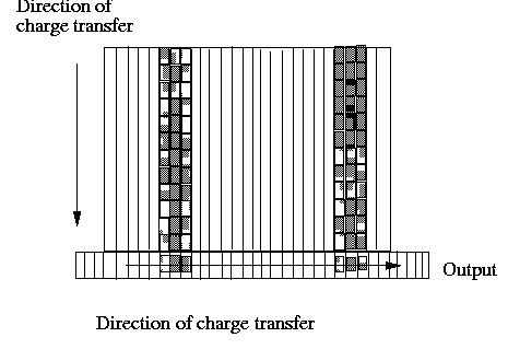
necessary to understand how the CCD is read out. As shown below, the
CCD will be read out by clocking each row down the CCD until it reaches
the serial (readout) register. Once in the register, pixels are shifted
across, one at a time, into the readout amplifier.
EIS will have two CCDs, one detecting the long wavelengths and one detecting
the short wavelengths. To improve readout time and to provide some redundancy,
each CCD has two read out ports, one at the bottom right of the CCD and
one at the bottom left.
| CCD windows |
When defining an imaging sequence, windows may be defined for each image
so that it is possible to select only the lines or
groups of lines that are directly relevant. The number of windows allowable
is still TBD.
However, it is difficult to implement such a potentially large number
of windows within the camera electronics. Consequently, a reduced set of
windows will actually be implemented within the camera itself. On most
occasions, the windowing adopted within the camera will be completely transparent
to the user, but the time required to clock out the CCD will vary depending
on the window sizes and positions selected. Hence, any calculations of
actual CCD image readout time will need to use the actual size of the hardware
windows (which will be set by the Instrument Control Unit (ICU) based on
the user defined software windows).
| Implementing CCD windowing in hardware |
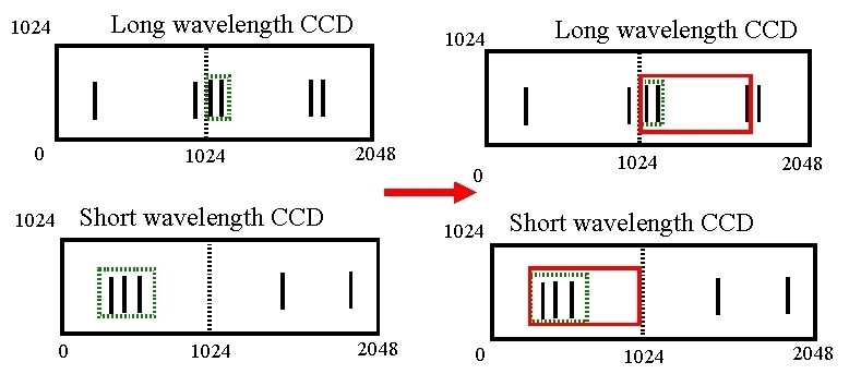
There are two windows per CCD, one for each half of the CCD. The figure below shows the two CCDs, with a number of spectral lines spread across each CCD. The spectral lines required have been defined within a window (shown as a dotted green line). Each window is specified in terms of its height in rows (up to a maximum of 512 rows) and its width in pixels (up to a maximum of 1024 pixels). Thus, to clock out the entire spectrum, a window width of 1024 pixels and a window height of 512 rows should be specified for each window. To simplify the electronics design, each hardware window must be the same height (in rows) and the same width (in pixels).
This means that the window defined in hardware must be large enough
to cover all possible spectral lines, as shown below.
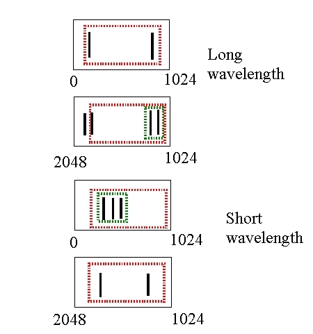
In effect, the overall size of the window can be determined by superimposing the positions of the required spectral lines onto just one of the CCD halves. This is shown below.
| Calculating the readout times |
Calculating the readout time of the CCD for a hardware window is straightforward, but again requires a brief understanding of how the CCD hardware actually operates. This is explained below, with a couple of example calculations.
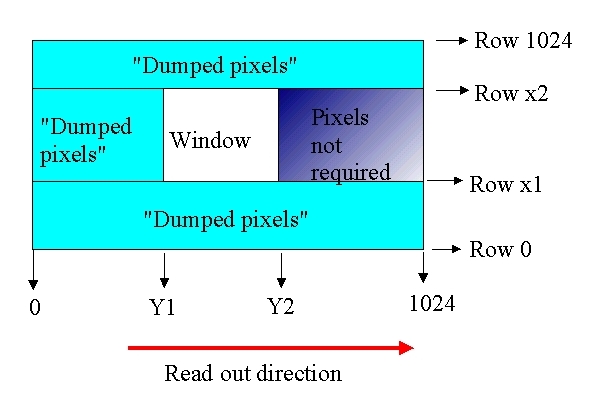
The final window coordinates are from pixel Y1 to pixel Y2 in the spectral direction and from row x1 to row x2 in the spatial direction. Pixels are read out from left to right.
Rows from 0 to x1 do not need to be measured and can be quickly dumped (i.e do not need to be clocked through the output amplifier). This will take about 30us per row.
It is not possible to "dump" individual pixels, only entire rows at a time. Consequently, it is not possible to dump the pixels between rows x1 and x2 and which occur before the readout window. However, it is possible to quickly clock these pixels through the output amplifier without actually digitising them. This will take 400ns per pixel.
The pixels within the readout window must be clocked into the output amplifier and digitised. This will take 2us per pixel.
Once the pixels within the readout window have been read, the following pixels are not required. Consequently, the row can now be dumped. Again, this will take 30us.
Finally, the rows above the readout window (i.e from row x2 to row 1024) do not need to be clocked through the amplifier and can be dumped at 30us per row.
To read out the CCD in the above case will take:
| the number of rows below the readout window x 30us | (0 to x1) x 30us |
| + | + |
| the number of rows within the readout window x the number of pixels before the readout window x 400ns | (x1 to x2) x (Y2 to 1024) x 400ns |
| + | + |
| the number of rows within the readout window x the width of the readout window x 2us | (x1 to x2) x (Y1 to Y2) x 2us |
| + | + |
| the number of rows within the readout window x 30us | (x1 to x2) x 30us |
| + | + |
| the number of rows above the readout window x 30us | (x2 to 1024) x 30us |
For a window from pixel 250 to 300 (i.e 50 pixels wide), starting
at row 100 and 512 rows high, would take the following time to read out:
(30us x 100) + (512 x 100 x 400ns) + (512 x 50 x 2us) + (512 x 30us)
+ (412 x 30 us) = 0.1s
Whereas if the window goes from 700 to 1000 (i.e 300 pixels wide), starting
at row 100 and 512 rows high, the read out time will be:
(30us x 100) + (512 x 700 x 400ns) + (512 x 300 x 2us) + ( 512 x 30us
) + (412 x 30us) = 0.48s
Thus, the eventual CCD readout time depends crucially on the window size and position.
This page was last changed on 7 November 2000 by Chris McFee