
Pre-launch ground calibration of the UV-Grism
Relating the wavelength scale and sensitivity of the spectral orders
Report by Paul Kuin
Date:2008/07/21
Version: 1.1, converted to Sphinx 2013-06-11
Introduction
In November 2002, the Swift UVOT underwent a ground calibration at the NASA GSFC. During this calibration, images and spectra were taken. The UV grism data discussed in this document are those taken for the redundant system which is the current operational system.
Observations and processing
The instrument was mounted on the optical bench of the test system with the artificial source at, or very near, the boresight (unless the telescope was rotated on the gimbal for special observations). The light source was a platinum/Neon lamp. A graph paper with the spectrum of the lamp with a resolution of 100Å/2cm was provided. Tests were taken with either a blank filter, or one of three narrow-band filters in the path of the beam that fed the telescope. The narrow band filters are known as NB193, NB214, and NB260. The document with the specifications of the band passes of the filters is not available to us. The effective bandpass of each band was reconstructed, using a combination of the observer notes provided, the zemax solution for the boresight, and tables of the Pt/Cr/Ne spectrum as provided by NIST on the WWW. The observations are available as event data in FITS files. The files were read in using an IDL routine to construct images, which are 2048x2048 pixels. The image X and Y were transposed in order to obtain the same geometry as the in-orbit data. The raw images were converted into detector coordinate images by appending headers to the raw images, and processing with the UVOT/ftools software (swiftxform).
In table 1, the observations of the current UV grism (redundant prism 1) that were used have been listed. Open items were not recorded.
Table 1. Observations used
| obs # | Path | filename | target | metallic neutral density NDm# | Narrow band filter λ | lamp mA | notes |
|---|---|---|---|---|---|---|---|
| 0128 | 20021116_grism1_r/* | 1037438536_0 | 5μ pinhole | NB214 | on-axis | ||
| 0129 | 20021116_grism1_r/* | 1037440745_0 | 5μ pinhole | NB193 | short time exposed with clear filter in addition to long exposure in NB193 | ||
| 0130 | 20021116_grism1_r/* | 1037443124_0 | 5μ pinhole | clear | NB260 | 14 | observer mistakenly notes a separation of the peaks λ2550 and λ2559 (These appear to be the λ2559+2550 blend and λ2531 instead) |
| 0228 | 20021118_grism1_r/* | 1037602492_0 | 5μ pinhole | clear | NB193 | 10 | wheel position 200 |
| 0232 | 20021118_grism1_r/* | 1037606076_0 | 5μ pinhole | clear | NB214 | 12 | wheel position 200 |
| 0236 | 20021118_grism1_r/* | 1037610501_0 | 5μ pinhole | clear | NB260 | wheel position 200 |
Table 2: line identifications
| Narrow band filter | observed wavelength | line identifications (blends) | |
|---|---|---|---|
| NB193 | 1883 | (weak peak) | 1883.0 |
| NB193 | 1916 | (main peak) | 1911.7,1916.1 |
| NB193 | 1930 | (strong secondary peak) | 1929.2,1930.0,1937.4 |
| NB193 | 1971 | (weak peak) | 1969.7,1971.5,1978.8 |
| NB193 | 2036 | (weak peak) | 2030.5,2032.4,2035.8,2036.5,2041.6 |
| NB214 | 2175 | (weak peak, blends with 2203) | 2174.7 |
| NB214 | 2203 | (secondary peak) | 2202.3, 2209.5 |
| NB214 | 2246 | (main peak) | 2245 |
| NB260 | 2631 | (secondary peak) | 2631 |
| NB260 | 2660 | (main peak) | 2559.45,2650.8 |
In the following plot, the total counts observed in three observations (128,129,130) with three different filters have been combined and plotted as function of wavelength. Note that the spectral range probed is from about 1850 to 2800 Angstroms.
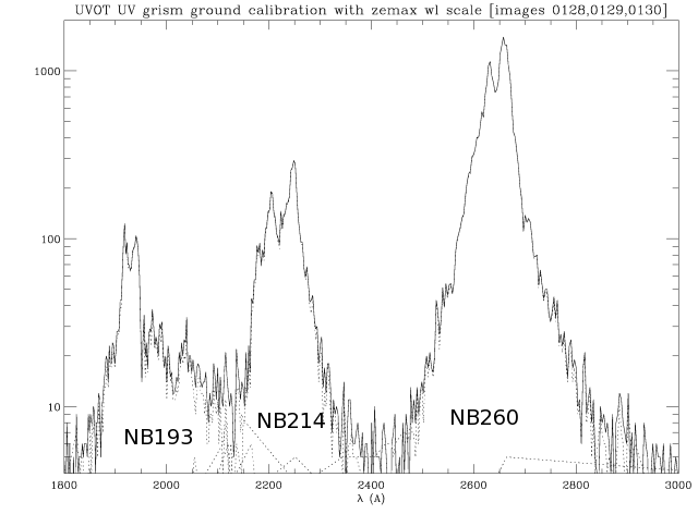
Figure 1. Combined in one figure are three observations with the measurements from each filter along the dispersion direction in the first order. The observations were taken in sequence with the source on-axis. The dotted lines show the individual filter contributions.
A contour plot shows the location of the flux on the image.Once again observations in three filters were combined in one image.
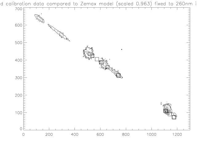
Figure 2 shows the relative positions (from right to left) of the zero, first, and part of the second order, in the calibration observations. The zemax model calculations, with pixels scaled by 0.963, have been plotted as squares symbols at wavelengths ranging from 1900-2600 Å. The zemax model was shifted to fit the first order. As can be seen, the zero order shows a slight offset from the model position. This zemax model was calculated with a 3.8 degree correction.
Table 3 lists the (detector) image coordinates of the main peaks derived from examining the data in “DS9”. These have FITS coordinates defined by:
CRPIX1=996.5
CRPIX2=1022.5
CRVAL1=0.
CRVAL2=0.
CDELT1=0.009075
CDELT2=0.009075
CTYPE1= 'DETX' /X coordinate type
CTYPE2= 'DETY' /Y coordinate type
CUNIT1 ='mm'   / X coordinate units
CUNIT2 ='mm'   / Y coordinate units
Table 3: Coordinates of peaks (DET image)
| Filter | obs | Zeroth order | First order | Second order | Third order |
|---|---|---|---|---|---|
| NB193 | 129 | (1650.1,562.8) (1641.4,568.3) | (1207.3,807.0) (1200.0,811.0) | (781.3,1039.5) (768.5,1046.0) | (351.0,1272.4) (339.0,1277.5) |
| NB214 | 128 | (1605.9,592.9) (1603.0,594.0) | (1108.8,864.0) (1095.3,871.8) | (619.5,1129.0) (596.8,1142.0) | (132.3,1394.0) (102.5,1413.3) |
| NB260 | 130 | (1579.1,610.5) | (987.4,933.0) (979.2,937.9) | (395,1255) (390,1257.4) | off detector |
| NB193 | 228 | (1638.5,576.8) | (1204.5,814.5) (1198,817.5) | (796.5,1035.0) (780.0,1045.5) | (360.5,1275.0) (345.0,1280.0) |
| NB214 | 232 | (1604.5,600.0) (1598.9,602.1) | (1105.5,871.5) (1093.0,878.5) | (618.0,1136.5) (593.5,1150.0) | (108,1411) (90,1421) |
| NB260 | 236 | (1578.5,615.9) (1576,4,618.5) | (984.1,940.5) (977.3,944.5) | (395.4,1260.3) (388.8,1266.1) | off detector |
The table 4 lists the distances (along the dispersion) of the main lines of each narrow-band filter observation between the first and zeroth orders.
Table 4: measurements of order distances along dispersion direction (DET image)
| filter | obs | line | zero-first | first-second | first-third |
|---|---|---|---|---|---|
| NB193 | 0129 | 1916 | 505.7 | 485.3 | 975 |
| NB193 | 0129 | 1930 | 503.7 | 419.4 | 979 |
| NB214 | 0128 | 2203 | 566.2 | 556.4 | 1112 |
| NB214 | 0128 | 2246 | 578.7 | 567.0 | 1131 |
| NB193 | 0228 | 1916 | 502.0 | 463.8 | 961.5 |
| NB193 | 0228 | 1930 | 476.1 | 970.3 | |
| NB214 | 0232 | 2203 | 568.1 | 554.9 | 1134.5 |
| NB214 | 0232 | 2246 | 576.5 | 568.5 | 1140.3 |
| NB260 | 0236 | 2631 | 677.3 | 670.0 | |
| NB260 | 0236 | 2660 | 682.1 | 674.3 | |
| NB260 | 0130 | 2631 | 674.3 | ||
| NB260 | 0130 | 2660 | 670.3 |
A second order polynomial fit ( \(D(pix) = \Sum_i C_i \lambda^i,\ \lambda in Å\) ) to the distance from the first to the zeroth,second, and third orders as a function of wavelength was made. The coefficients are:
Table: Polynomial coefficients
| . | D(first-zero) | D(first-second) | D(first-third) |
|---|---|---|---|
| c0 | 241.6 +/- 52.2 | -155.5 | -2733 |
| c1 | 0.0595 +/- 0.0463 | 0.375 | 3.136 |
| c2 | (4.00 +/- 1.01) 10-5 | -2.374 10-5 | -6.3 10-4 |
The result can be seen in Figure 3.
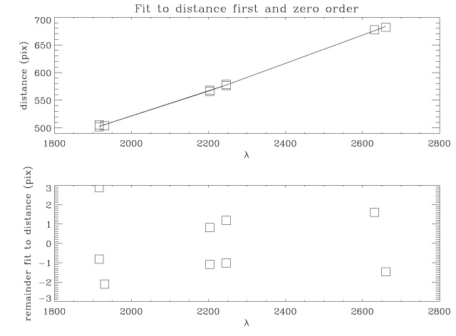
Figure 3: the fit to the measured distances from the ground calibration.
The zemax model dispersion relative to 260nm in first order was plotted against the measured dispersion from the ground calibration. The corresponding zemax numbers, are presented in Table 5 for different scale factors. The scale factor of 0.963 +/- 0.003 was derived from fitting the wavelength scale to the first order spectra of WR52 and WR86. The distances between zero and first order for the 0.963 model are compared to those from the ground calibration in Figure 4. At wavelengths below 2000Å the zemax model is not reliable. It can be seen that the measurements for wavelengths larger than 2000Å are on the average four pixels less distant in the ground calibration. For comparision the zemax results, scaled by a factor of 0.957 have been included, which show a much better fit to the ground calibrated distances above 2000Å. A scale factor of 0.957 is two sigma from the result from fitting the first order wavelength scale, and is thus not inconsistent therewith. It must be kept in mind, that to derive the distance, the measured coordinates of the peaks were used. Since there is a slight offset of the actual zero order from the Zemax model, while the model distances include the offset, there is no reason to adjust the pixel scale factor from the 0.963 value.
Table 5. Zemax model distances along the dispersion for varying scale factors compared to the measured ground calibration
| .ℷ(Å) | 1.0 | 0.963 | 0.957 | measured |
|---|---|---|---|---|
| 1916 | 518 | 499 | 496 | 504 |
| 1930 | 522 | 502 | 499 | 504 |
| 2203 | 593 | 571 | 568 | 567 |
| 2246 | 604 | 582 | 579 | 578 |
| 2631 | 706 | 680 | 676 | 677 |
| 2660 | 714 | 687 | 683 | 682 |
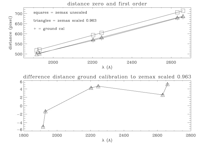
Figure 4: comparison ground calibration zero-first order distances to zemax with scale factor = 0.963.
The wavelength scale of observations might now be extended to the zero order, allowing to determine the wavelength of the uvotgraspcorr anchor point, and a photometric calibration for the zero order.
Distance of the first to second order as derived above from the ground calibration, was also compared to the zemax model results. Like for the zero-first order distances, the wavelengths below 2000Å do not fit very well with the zemax predictions, and the model with the scale factor of 0.963 fits quite well. It may be that the 1916Å is a misidentification, or that it is not very reliable since it is very noisy.
Table 6. Zemax model distances along the dispersion for varying scale factors compared to the measured ground calibration
| λ(Å) | 1.0 | 0.963 | 0.957 | measured |
|---|---|---|---|---|
| 1916 | 504.4 | 485.7 | 482.7 | 442 +/- 17 |
| 1930 | 508.1 | 489.3 | 486.2 | 480.7 +/- 3 |
| 2203 | 580.0 | 558.5 | 555.0 | 555.7 +/- 1 |
| 2246 | 591.4 | 569.5 | 565.9 | 567.8 +/- 0.6 |
| 2631 | 695.0 | 669.3 | 665.2 | 670.1 +/- 0.2 |
| 2660 | 703.1 | 677.1 | 672.9 | 672.5 +/- 2 |
The total counts in each filter give a good measurement of the relative sensitivity in the different orders, provided the coincidence loss is negligible. Inspecting the brightest features, no evidence for the kind of pattern we see in sky observations is seen. In fact, the source seems more extended. The source aperture may have been larger than a source on the sky depending on the distance of the pinhole to the instrument. It is therefore possible that some photons have been lost through the anto-coincidence code, which rejects detections that are within one frame in neighboring pixels. The 0130 observation appears to be approximately 2000 seconds long (no record was kept) , and the highest peak rate is about 27000 in the 260NB filter, spread out over 600-800 pixels. The maximum rate is therefore about 24000/2000/600 = 0.02 c/s/pixel. This is small enough that coincidence losses are negligible.
Table 7a. Measured relative sensitivities between orders: net counts by filter and observation
| . | NB193/0129 | NB193/0228 | NB214/0128 | NB214/0232 | NB260/0130 | NB260/0236 |
|---|---|---|---|---|---|---|
| zeroth order | 240 | 319 | 367 | 183.4 | 10545 | 1900 |
| first order | 2572 | 4103 | 5010 | 2630 | 24232 | 4274 |
| second order | 2063.5 | 3250 | 2025 | 1158 | 5434 | 935 |
| ratio | ||||||
| Zeroth/first | 9.3+/-1.5 | 7.8+/-0.5 | 7.3+/-0.5 | 6.9+/-0.5 | 43.5+/-0.4 | 44 +/- 1.5 |
| (percent) | ||||||
| Second/first | 80+/-2 | 79.2+/-1 | 40.4+/-1 | 44+/-2 | 22.4+/-0.5 | 22 +/- 1.5 |
Table 7b. Measured relative sensitivities between orders: net counts by filter and derived zeroth and second order effective areas (in cm2)
| . | NB193 | NB214 | NB260 |
|---|---|---|---|
| ratio | |||
| Zeroth/first | 8.6 +/- 1 | 7.1 +/- 0.4 | 44 +/- 0.5 |
| Second/first | 80 +/- 1 | 42 +/- 1 | 22 +/- 0.5 |
| zero order effective area | 0.51 | 0.76 | 5.6 |
| first order effective area | |||
| (cm2) (adopted from CALDB) | 6.0 | 10.7 | 12.7 |
| second order effective area | 4.8 | 4.5 | 2.8 |
The extraction of the counts was done with a width of 25 pixels, which included most of the signal. The reason for such a wide extraction width is that the source is slightly extended due to the finite aperture. The effective areas were derived from the ratios and the effective area in the CALDB with latest update dated 2007-07-11, and are mainly included to give an idea of their size.
Point Spread Function
The point spread function in the zero and second orders was calculated with Zemax. A summary is given in table 8. The shape of the PSF is a peak with a horse-shoe like extension. It has been fitted with a 2-D gaussian, but I only list the radial widths. Listed are the full width at half maximum, as well as the maximum radius to which the PSF extends. The PSF needs to be studied further, in particular the extend along and across the dispersion, and the energy contained within certain limits which have to be defined intelligently. As such, this table should anly be taken as an indication of the character of the PSF variations.
Table 8. Summary of Zemax calculations of the PSF wavelength (Å)
| wavelength | zeroth order FWHM (pix) | zeroth order maximum radius (pix) | second order FWHM (pix) | second order maximum radius (pix) |
|---|---|---|---|---|
| 1900 | 9.0 | 19 | 5.9 | 12 |
| 2000 | 8.4 | 18 | 6.5 | 14 |
| 2100 | 7.7 | 17 | 7.7 | 16 |
| 2200 | 7.4 | 16.3 | 8.7 | 19 |
| 2300 | 7.1 | 15.7 | 10 | 22 |
| 2530 | 6.5 | 14.6 | 14 | 29 |
| 2900 | 5.9 | 13.6 | 22 | 46 |
| 4000 | 5.3 | 12.1 | 63 | 127 |
| 5500 | 5.0 | 11.5 | — | — |
Although below 1900Å the zero order dispersion is approaching one Å/pixel, the PSF of the spectrum is increasingly broadened. This is consistent with observations of WR52, which showed very broad bumps. A detailed comparison, using the wavelength scale from the data above, must still be made.
In the second order, the PSF becomes very large above 2500Å. A similar occurrence may happen in the first order above ~ 5000 Å.
Summary
- The wavelength scale in the zero and second order has been determined relative to the first order, using the on-axis observations taken during the ground calibration in the 1900-2700Å range.
- The relative sensitivity of the zeroth and second order with respect to the first order has been determined from the ground calibration measurements.
- The point spread function in the zeroth and second order was determined from the Zemax optical model, and shows that at short wavelengths the lines in the zero order are the broadest, and the lines in second order are the broadest for the longest wavelengths.
References
- “Atlas of the spectrum of a Platinum/Neon Hollow Cathode Lamp in the region 1130-4330Å,” J.E.Sansonetti, C.J Sansonetti, J.Reader, N. Aquista, A.M. Sansonetti, and R.Dragoset, J.Res.Natl.Inst.Stand.Tech. 97,1-212 (1992).
- The ground test document: “Grism Resolution; Swift optical test procedure”. SWIFT-UVOT-145-R01, 10 Nov. 2002.
- accompanying Spreadsheet 02_11_15_psf_data_sheet_final.xls.
- accompanying CD-ROMs with data from the ground calibration.
- accompanyin chart with spectral output of Pt/Cr/Ne Lamp, dd. 3-11-2002, Lamp S/N NY10258A.