CCD Group |

|
|
|
|
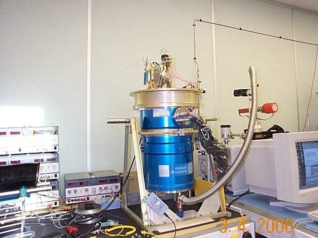
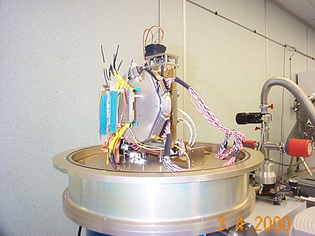
Above is a block diagram of MSSLs CCD Test Facility, which is situated in MSSLs class 100 cleanroom. The CCD and its FPA card are mounted on an X-Y stepper motor system in a vacuum chamber and the CCD is cooled using a flexible attachment to a LN2 reservoir which is built into the chamber. A window in the chamber wall permits the CCD to be illuminated from outside the chamber. This allows various optical setups to be used and changed (e.g. pinpoint illumination, flat-field, focussed image) without disturbing the CCD. The window and optical bench are in a dark enclosure to eliminate external light. The X-Y stepper system allows the CCD to be moved in the optical beam to expose different areas of the CCD to the same optical flux, e.g. to perform flat-fielding, and also allows a calibrated photodiode to be placed in the beam for flux measurement.
Heaters on the support plate for the CCD allow the temperature to be controlled. A 4-wire rhodium-iron thermometer is used to measure the temperature.
The experiment control and data acquisition PC communicates with the stepper motor controller via an RS-232 serial link.
The ROE generates the clock pulse sequences to shift and readout the CCD. It also performs CDS on the video signals from the FPA card, digitises the video and buffers the digital data. The ROE is highly flexible, allowing the PC to control integration, windowing, binning , readout direction, etc...
The PC contains a custom-built ISA card to interface with the ROE. This card has several functions:-
The bias/jitter-clocking box allows the PC to control CCD bias voltages and jitter/dither-clocking.
The whole setup is controlled from the PC using the IDL programming
language. This allows interactive or program control and seamless inclusion
of graphics for near-realtime display. The high-level software is written
in IDL, while some low-level routines are written in C and called as DLLs.
Another benefit of IDL is that the same analysis programs can be run locally
on the PC or on the MSSL network (SUNs and DEC Alphas).
 |
 |
|
|
|
Back to:
|
|
|
 |
|
|
|
|