Technical note: MSSL/SLB-EIS/TN12.0
Author: C J McFee
Date: 17 May 2001
Shielding requirements for EIS - initial sectoring studies
Introduction
The typical radiation dose which may be encountered assuming a 4p spherical aluminium shield was calculated using the SPENVIS space radiation program. Using data provided by Marconi it was possible to say that the flat band voltage shift caused by the ionising radiation dose would not be sufficient to cause problems with CCD operation. The effect of the proton dose on the device CTE was not so clear. However, very basic modelling was conducted using the incident proton values obtained by SPENVIS and it was considered that the potential change in CTE was tolerable (although there were large inaccuracies associated with these calculations).
Tolerable radiation and proton flux values
It is not possible to predict the variation in CTE with any such accuracy. However, it is considered that a loss of about 5% of charge from each pixel whilst clocking out the CCD could degrade the spectral resolution available from EIS. Consequently, a conservative estimate of 3.5% charge loss at -40°C. has been adopted. This corresponds to an overall proton dose of around 3.5x10⁹ protons/cm2.
Calculation of optimum shielding configurations
However, the simplicity and ease of use of SPENVIS means that it can be used to provide an initial estimation of the optimal overall shielding geometries.
Example
Figure one shows the spacecraft and EIS made up from a number of simple components. The spacecraft is represented by a cylinder, with a nominal overall shielding of 3mm equivalent of Aluminium. The structure of EIS is represented by a box, and the overall shielding provided by the box is a nominal 0.01mm equivalent of Aluminium. Overall, there are not enough components to completely model the entire shielding around the detectors in a single calculation. Consequently, a number of different calculations have been combined to give an overall sector calculation. Full dimensions used for all components are listed in table one. Note that in this example I have assumed that the spacecraft will provide the equivalent of 3mm Aluminium shielding, whereas the EIS structure will provide virtually no shielding (0.01mm).
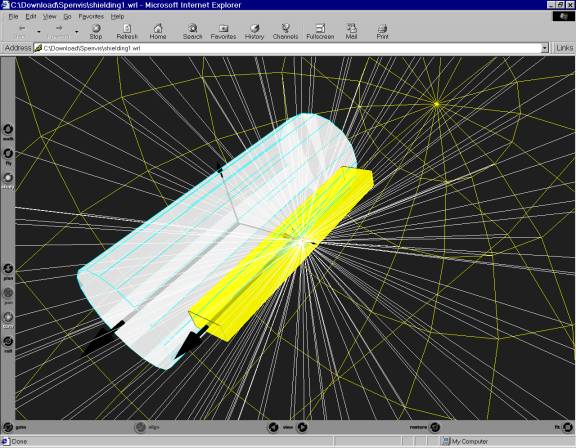
Figure one - the spacecraft with EIS attached
Figure two below shows the ray trace for a nominal point at the centre of the shielding ?box?.
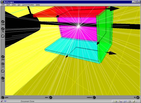
Figure two. A ray trace
showing the shielding provided by the box, in front of and behind the CCD.
The percentage of the overall field of view with a particular shielding value is shown below in figure 3 for the 3mm Aluminium box. Note that the plot does not include any shielding in front of the CCDs (to allow light to reach the CCDs).
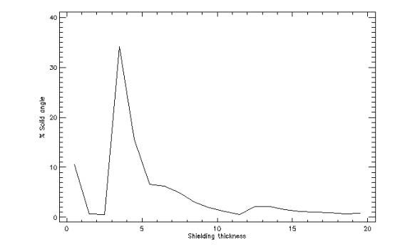
Overall, about 10% of the total field of view does not ?see? any shielding at all. As expected, the median shielding thickness encountered is 3mm but a majority of views will actually encounter a thicker shielding than the 3mm shielding that would be encountered for spherical shielding.
Radiation and proton flux for box of 3mm thickness
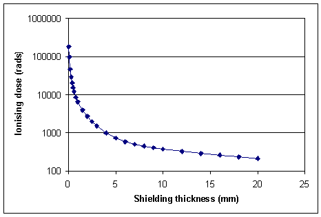
Figure four, the variation of ionising dose with shielding thickness
Similar results are obtained for the proton dose where a mission (five years) proton dose of 2.4x10¹⁰ protons/cm2 is found. In the case where at least 1mm shielding is seen by all sectors, then a mission proton dose of 5.5x10⁹ protons/cm2 is found. As radiation damage (and hence the increase in the potential charge loss) is directly proportionally to the proton flux, a value of 5.5x10⁹ protons/cm2 will correspond to a charge loss of about 5.5% which is still above the preferred charge loss discussed earlier.
The above example shows how it is important to ensure that virtually all of the CCD is shielded to some extent, as even a small amount of shielding (for example, 1mm Aluminium equivalent thickness) can dramatically reduce the radiation dose. Consequently, if (as is likely) the total mass available is critical, then it is important to ensure that all the CCD sees at least 3mm shielding of Aluminium. Only then should any additional mass be used to increase the shielding thickness of any particular sector.
In the example above, assuming a density of Aluminium of 2.7 gcm-3 the mass of the above shielding (including 1mm thick Aluminium in front of the detector) would be 202g (i.e within the current mass allocation but providing insufficient shielding).
Of course, it will not be possible to achieve full 4p shielding close to the CCD as viewports will need to be cut into the shielding to allow the spectrum to fall onto the CCD. However, it is very important that every part of the CCD can see at least some shielding. The best solution would be to place further baffles (as cups) in front of the aluminium shielding to restrict the field of view further. Ideally, the baffles would restrict all of the field of view apart from the minimum required to see the grating itself (which itself will provide a shielding effect).
Table one: the parameters used for modelling the radiation dose in the example above.
|
Spacecraft
(cylinder)
|
Diameter 1.5m
|
|
|
Length 4m
|
|
|
Wall thickness 3mm
|
|
EIS
|
Width 50cm
|
|
|
Height 25cm
|
|
|
Length 3.2m
|
|
|
Wall thickness 0.01mm
|
|
Shielding backplate
|
Width 10cm
|
|
|
Height 60mm
|
|
|
Wall thickness 3mm
|
|
Top and Bottom plates
|
Width 10cm
|
|
|
Length 50mm
|
|
|
Wall thickness 3mm
|
|
Side plate
|
Height 60mm
|
|
|
Length 50mm
|
|
|
Wall thickness 3mm
|