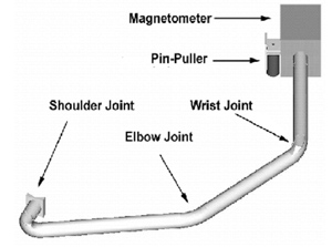
Booming diversity
AXIOM will need two booms: one for the magnetometer and one to support the plasma package. The estimated masses of the instruments are 3.2 kg and 13 kg respectively, as stated in AXIOM's proposal document. The estimated boom lengths are 3 m for the magnetometer boom and 1 m for the plasma package boom. We would like to choose a preliminary design for each boom.
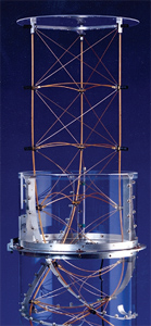
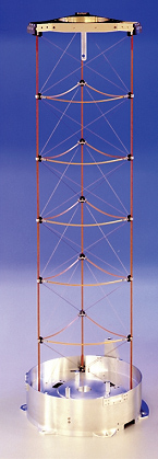
There are at least five major types of space booms that can be used for a number of applications, mainly for deploying and supporting instruments (cameras, magnetometers, particle detectors), solar arrays and antennas (see images in the left column):
- simple booms
- hinged booms
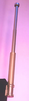
- telescopic booms
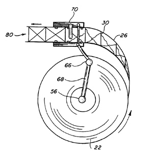
- "tape measure" booms
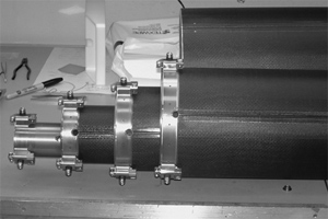
- coilable booms
Their advantages and disadvantages are presented in the following table.
| Boom | Advantages | Disadvantages |
|---|
| Simple boom |
- Simple
- Easy to manufacture
- Cheap
- Reliable
|
|
| Hinged boom |
|
- Hinges need to be latched
- Less reliable
- Little control over deployment
|
| Telescopic boom |
- Compact
- Can be long
- Controlled deployment
- Can be retracted
|
- Complex
- Expensive
- Even less reliable
|
| “Tape measure” boom |
- Compact
- Can be very long
- Controlled deployment
- Can be retracted
|
- Complex
- Expensive
- Even less reliable
- Limited strength
|
| Coilable boom |
- Compact
- Light
- Can be very long
- Controlled deployment
- Can be retracted
|
- Complex
- Expensive
- Even less reliable
|
While a simple boom is the cheapest and most reliable solution, it may not be suitable for supporting the magnetometer because the latter needs to be far away from the magnetic field created by the spacecraft. This would require a very long boom (estimated to about 3 m) that would need to be accommodated on a payload of less than 2 m long. An intermediate solution in terms of cost and reliability would be the hinged boom. Finally, to obtain a reduced boom length in a stowed configuration, one may consider more expensive and more complex telescopic, "tape measure" or coilable booms.
Coilable booms are a popular choice for supporting magnetometers, probably because they are light, compact when stowed but very long when deployed. Since magnetic cleanliness is a concern for AXIOM, we may consider a long coilable boom for the magnetometer to keep it away from the payload's magnetic fields. As for the plasma package boom, simple or hinged booms are a good choice because of their relative simplicity.
Short is beautiful
Let us consider a hexagonal payload of diameter D and height a. Let x be the FOV of the instruments (in radians). We can calculate the minimum required length L for the boom so that the spacecraft does not obstruct the FOV of the instruments. Simple trigonometry gives us the following formula for the minimum length of the boom:
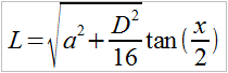
From consideration of the Vega fairing's size envelope, and from inspection of the payload diagrams in the AXIOM proposal document, we may assume a module of 1.3 m in height, 2.1 m in diameter and a field of view of 30o and hence the minimum length for the boom is 38 cm according to the formula. Since the estimated boom length is smaller than the length of the payload, we may consider a deployable simple boom rather than a more compact hinged boom. Moreover, there is no need to use the more complex coilable or telescopic booms for this relatively small length. The simple boom will have the advantage of being cheaper and a lot more reliable. It will be attached to the body of the spacecraft during the launch phase and will be deployed during the perigee raising phase of the mission or once AXIOM reaches the L1 point.
Material world
The most common materials for space booms are steel, aluminium alloys, titanium alloys, magnesium alloys, beryllium and Carbon Fiber Reinforced Polymer (CFRP). The following factors must be taken into account when choosing materials for space booms:
- Mass: biggest design driver. Aluminium, magnesium, beryllium, CFRP are light materials.
- Stiffness: the deformation of the boom is a concern since it will displace the centre of mass of the spacecraft which in turn may compromise its attitude control and the pointing accuracy of the instruments and antennas on board. Titanium, beryllium and CFRP are strong and stiff.
- Cost: is a less important design driver because the cost of a boom is very small compared to the total cost of the mission. Steel, aluminium and magnesium are cheap materials.
These parameters can be combined into a materials choice matrix (see figure below). The bottom-left corner represents the ideal type of material - light and cheap. The top-right corner is the opposite and the other two quadrants are just trade-offs in terms of mass or cost. Each diamond represents a type of material and its size is a measure of stiffness (Young's modulus) of the corresponding material. It is clear from the diagram that aluminium and magnesium alloys are the best in terms of mass and cost. If we add stiffness as a third parameter, we might consider CFRP or beryllium. Steel and titanium alloy are too heavy compared to the others which disqualifies them since we have decided that the mass criterion is the most important.
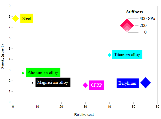 Cost-density-stiffness diagram In conclusion, aluminium and magnesium alloys seem to be the best choices for the boom because they are fairly light and cheap. Additionally, aluminium has a longer history of space flights and is more widely used for space booms. If more stiffness is needed, CFRP is the best candidate. Beryllium can also be an alternative for bringing even more stiffness if extra cost is not an issue but it needs to be operated with great care because of its toxicity.
Top model
The plasma package boom can be modelled as a cantilever beam of length L using simple beam theory [9]. One end of the boom will be attached to the body of the spacecraft and therefore the angular deflection at this point will always be 0. The other end will be free and will support the instruments represented by a point load P. Under such a load the boom will deflect into a curve and the amount of deflection will depend on such parameters as the boom's length, shape and composition. The angular deflection θ of the free end is the angle between the boom's neutral axis (axis passing through the centre of the unloaded boom) and the axis tangent to the free end of the deflected boom.
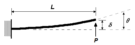 Model of the boom. Credit: Russ Elliott [10]According to Gere and Timoshenko (1997) [9], the following equation describes the angular deflection of the boom:
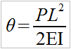
P is the point load on the free end of the boom (we will assume 100 N in this study)
L is the length of the boom
E is the Young's modulus of the material (measure of its stiffness)
I is the second moment of area of the boom's cross section and is given for a circular cross section by

r is the radius of cross section
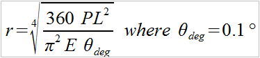
The choice of the radius of cross section is dictated by the requirements on the maximum allowable deflection of the boom. The plasma package is required to have an angular resolution of less than 2o. We may safely assume that the boom is allowed to deflect for no more than 0.1o. We can now define the radius of cross section that will satisfy this requirement as a function of the boom length using the previous equations:
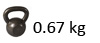
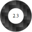
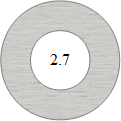
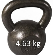
Let us now estimate the final size and mass of two booms: the 38-cm boom defined previously as the minimum-length boom and the 1-m boom suggested in AXIOM's proposal which takes into account design margins. In the following table, the darker circles represent CFRP booms and the brighter ones correspond to aluminium.
| Length (m) | Cross section radius (cm) | Mass (kg) |
|---|
 38 38 |
 |
 |
| 38 |
 |
 |
| 100 |
 |
 |
| 100 |
 |
 |
How to lose weight
Since mass is a crucial design driver, we might want to reduce it for the plasma package boom. An easy way to do this is to use a hollow boom whose cross section can be described by its outer radius rout and inner radius rin. While the choice of such cross section will result in a slightly decreased performance in terms of angular deflection, the gain in terms of mass is rather important, as shown in the table below where the inner radius is chosen to be 50% of the outer radius. While we achieve a gain of up to 1.54 kg for the aluminium boom, its maximum angular deflection for the same load of 100 N is now just 0.107o. This is only 0.007o bigger than the suggested requirement and can probably be tolerated because of the significant mass gain that is obtained by using a hollow boom.
Cross section
radius (cm) | Old mass (kg) | New mass (kg) |
|---|
 |
|
 |
 |
|
 |
 |
|
 |
 |
|
 |
Do It Yourself!
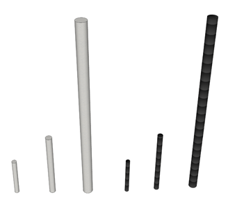 22-cm, 38-cm and 1-m booms compared Try specifying the parameters of the boom yourself and estimate the corresponding boom deflection in the following boom calculator.
|