 |
XMM |
 |
XMM |
 Contents
Introduction
The building of the mirror modules
The integration of the mirror modules
Images from the telescopes
Further Information
 Introduction
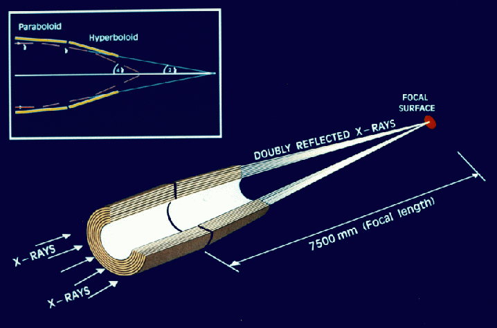
Each mirror shell is made of a parabolic and a hyperbolic section. This combination constitutes the Wolter design. As you can see above, on the top-left corner of the diagram, the use of the two mirrors shortens the distance to the point where the light focuses (the focal length) from around 30 m to to 7.5 m. At the same time, the two mirrors minimize astigmatism. The Wolter design is the X-ray equivalent to the optical Cassegrain design.
 The building of the mirror modules
Each mirror shell is made of nickel and it's coated with gold on the inside. Just like for any mirror, it is very important that these shells have the perfect shape and that the reflecting gold coat on the inside is even and smooth. For this purpose, highly polished shafts (mandrels) are employed as moulds around which the nickel shells are built. This is a long process:
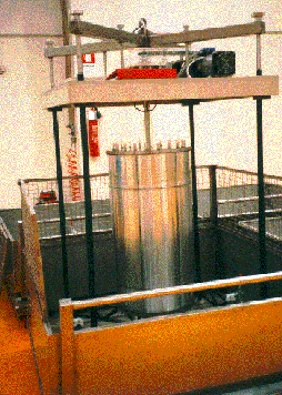 |
The highly polished mandrel is first coated with the gold surface which will become the mirror reflection surface. The mandrel is then submerged in an "electroform bath", in which a carefully controlled current makes the nickel dissolved in it "stick" to the mandrel at a specific rate. This process makes thin nickel shells slowly build up on the mandrel. The horizontal line you can see in the mandrel marks the end of the mirror shell |
| The shell is carefully removed from the mandrel by using differential thermal expansion. In this photo, the mirror shell (top) has just been separated from the polished mandrel (bottom). Here, it is just possible to see the inside of the mirror shell, with its gold reflecting surface shining red. The gold, which was first deposited on the mandrel, now comes off with the nickel shell, producing an inner highly polished surface with roughness comparable with that of the original mandrel. The mandrel is then cleaned before the next replication cycle. | 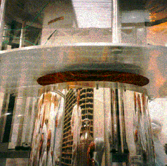 |
 The integration of the mirror modules
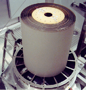 |
Here you can see how the mirrors shells are mounted on their support structure, called the "spider". The spider has little dents for the mirrors to sit on and help to retain their shape. |
| And here is a finished mirror module! This is the front, i.e. the side from which light enters. In front of the module one can see the "spider" on which the 58 mirror shells are mounted. This photograph was taken during mirror testing procedures at the Centre Spatial de Liege (CSL) in Belgium. |
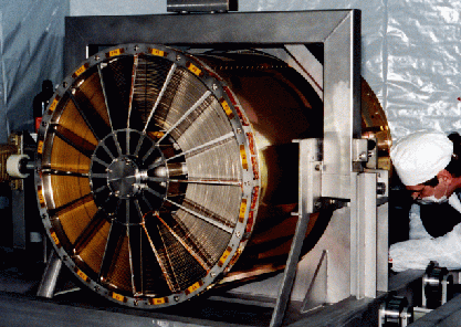 |
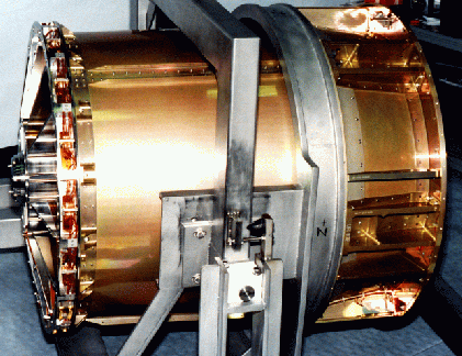 |
And here is a side view of the mirror module. They are about 70cm in diameter and about 60cm long (80cm with the baffle). |
 Images from the telescopes
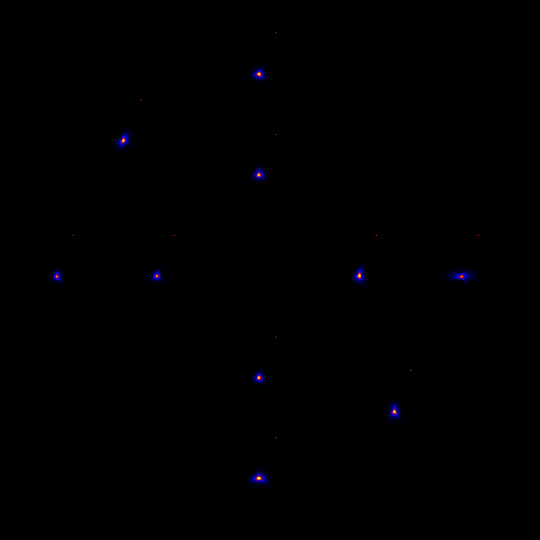 | Here is the so-called FM1 "dartboard": images of a point source obtained at several different offsets from the centre of the field of view. Note how their shape becomes less circular as we move away from the center. |
 Further Information
A description of the (expected) scientific performance of XMM and its instruments is provided in the XMM Users' Handbook.
Have a look at the ESTEC "Building XMM" web pages - they have many more XMM photos (including the FM1 first light images) for you to look at but be warned - they can take a bit to download! They are worth the wait though.
Find out more about the other XMM instruments: Back to the XMM schematic view.
These pages are adapted from various sources, mainly from the ESTEC page "Building XMM" and the Mullard Space Science Laboratory.
Various parties require acknowledgement for the photo material. Particular thanks are due to the XMM Project team at ESTEC, Centre Spatial de Liege, Medialario, Dornier, Max-Planck-Institut für extraterrestrische Physik (MPE) and the Space Research Organization of the Netherlands (SRON), Utrecht.
Last updated: Wed Mar 3rd 1999