 |
In addition to the filters, the OM filter wheel holds two grisms.
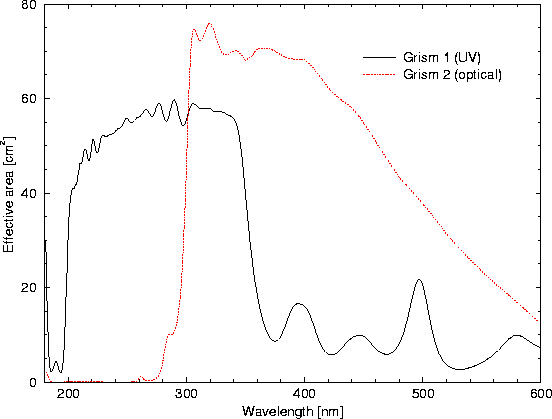
The throughput of the OM grisms depends on wavelength. This, folded with
the OM detector response, is displayed in Fig. 70.
The spectral resolution of the grisms is almost constant over their wavelength ranges. The former (in the UV) has a spectral resolution of ca. 0.5 nm per 1'' pixel, the latter (in the optical regime) 1 nm per pixel. The grisms can thus be used for moderate resolution optical and UV spectroscopy in conjunction with the X-ray observations. Only one grism can be used at any time. An image of the target area should be taken for identification of spectral sources prior to or after obtaining spectroscopic exposures with a grism. Note that grism observations currently cannot be modeled with SciSim.
The optical grism is blazed and the zeroth order image should accordingly be weak. The UV grism is not blazed, however, and ca. 1/3 of the light is expected to go into the zeroth order image, which is expected to be visible near the edge of the FOV when the first order spectrum is centred.