
![]()
![]()
![]()
![]()
![]()
![]()
![]()
![]()
The problems associated with molecular and particle contamination of spacecraft components, instruments and structures are well known and documented especially those that contain fine mechanisms and/or optics. This problem is severely exaggerated when the instrument is operating under space vacuum. When looking at contamination problems in a space environment there are two important contamination sources:
Particulate contamination.
Particulate contamination is basically the dust and other particles that is always present in our earth environment. Added to this other forms of contamination may also be present e.g. hair, skin particles etc.
Molecular contamination.
Molecular contamination in a space vacuum is bought about by the out gassing of materials used in the manufacture of the instruments and/or structures. Other significant molecular contamination sources found in the Earth environment (at atmospheric pressure) can be broadly grouped into four categories. These are:
- Acids - A corrosive material with a chemical reaction that of an electron acceptor.
- Bases - A corrosive material with a chemical reaction that of an electron donor.
- Condensables - (excluding water) boiling point above room temperature at atmospheric pressure
- Dopants - A chemical element which is capable of modifying the electrical properties of a semi conductive material
In order to keep both forms of contamination to a minimum strict cleanliness controls are maintained throughout all stages of production, assembly, test and integration and in the case of molecular out gassing, rigorous material selection and monitoring of contamination levels within the cleanroom using various methods.
To this end M.S.S.L make use of an on site class 100 laminar flow clean facility. Its design specification is such that cleanliness levels conform to the U.S Fed. Standard 209E. The cleanroom is validated every 6 months by an independent external contractor.
Description.
The M.S.S.L cleanroom is based upon the horizontal laminar flow design, with one complete end wall being a bank of HEPA (High Efficiency Particle Air) filters. The efficiency of the HEPA filters are rated at 99.997% for 0.1 micron diameter particles. The exhaust return air is recirculated via a room width filter bank in the ceiling at the opposite end of the HEPA filters. The ratio of recirculated air to fresh air intake is: 75% recirculated air and 25% fresh air intake. Additionally the fresh air intake is fitted with a fine dust pre filter and LUWA AFP gas adsorption filters capable of filtering most Airborne molecular contaminants. This ensures the cleanroom is isolated from external contamination events and has resulted in the MSSL cleanroom having an extremely low background AMC level. Details of background contamination levels can be found here.
HEPA filters.
HEPA filters cannot reduce the amount of contamination (both particulate and molecular)
introduced downstream of the filter. The primary sources of downstream contamination
come from:
- A person sitting generates about 100 000 particles per cubic foot
- Sitting down or standing up generates about 2 500 000 particles per cubic ft
- Walking generates about 10 000 000 particles per cubic ft
- Grinding, sweeping, welding (including soldering) adds billions of particle per cubic ft
- Two surfaces rubbing generates billions of particles per cubic ft
- An open, non-air locked door can add billions of particles per cubic ft
- Process equipment add particles
- Process materials add particles
- Maintenance activities add particles
- Construction residue can generates massive particles
- Silica gel can add billions of particles per cubic ft.
Thus the overall contamination control of the M.S.S.L. clean facility not only depends on the filtration system, but also depends upon the management of processes and activities that are introduced in the clean facility. The filtered air is temperature and humidity controlled to 19 deg C +- 1 deg C and 50 % Relative Humidity (RH) +-5%. These values are continuously monitored and recorded.
Cleanroom design/layout
The cleanroom is divided along its length in ratio 2:1 by a light proof stud partition. This provides two completely separate cleanrooms. The layout of the cleanroom is shown below. The larger of the two rooms is a conventional cleanroom and is known as the white cleanroom. The smaller room is completely blackened and light proof and is known as the dark cleanroom. The dark cleanroom is primarily used for optical work and was used for both the XMM Optical monitor and SWIFT UVOT assembly,optical alignment and testing activities.
The white cleanroom is divided into 3 zones, A, B and C. Zone A is located long the entire length of the HEPA filters and is the cleanest area of the cleanroom. Zone B is located in the centre of the cleanroom and zone C is at the entrance to the cleanroom. In practice, due to the design of the cleanroom Zone C will always be the more "contaminated" of the three zones. In practical terms zone A is usually well below 100 particles per cubic ft @ 0.3 micron diameter particles, but is also dependent on activity. The same applies to the other zones. There are two laminar flow benches located in the M.S.S.L. cleanroom, one is sited in zone B in the white cleanroom and the other is situated in the dark cleanroom in zone C. Both these laminar flow benches rate consistently with Class 10 (F.S 209E) or better.
External to the cleanroom is the Anteroom. The Anteroom has double doors with weighted grills to maintain over pressure in the Anteroom. These doors open directly into the cleanroom. If the doors in the Anteroom that lead into the cleanroom are opened at the same time as the doors to the entrance of the Anteroom then an audible alarm will be sounded. The Anteroom is used to change into and out of cleanroom garments.
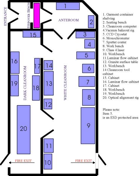
Cleanroom Layout.
©MSSL Created by Alex Rousseau last modified: February 2, 2004 11:56